Sunday 27 May 2012

6 Volt - 12 Volt Conversion for 1967 Vespa Sprint

12 Volt Vintage Vespa Conversion Wiring Kit
REF: http://www.allstyles-scooters.com/acatalog/info_74112KIT.html

The Mysterious 12V Wiring System

Found this online just now - finally a reference to a 12 volt wiring system for a Vespa VLB

Furthur Research is still needed - im slowly tracing out the wiring but there are a few mysteries to solve ;)

Vespa Wiring loom for CDI kit VBB/VBC Super/VLB Sprint

Vespa Wiring loom for CDI kit VBB/VBC Super/VLB Sprint thumbnail thumbnail

Details

Stock:
V1911A-CDI-2
Weight:
320 grams

Description

This wiring kit goes with our 12v VBB/VBC/VLB CDI (electronic ignition) kit using PX-style flywheel and Ducati-type CDI/coil unit, BUT only if you want to rewire the whole scooter. (The electronic ignition kit itself already includes a loom to add-on to your original wiring.) This kit includes:
  • wiring loom
  • modified horn/light switch
  • 12v brake switch
  • ignition switch with keys
You will have to include the key switch on your scooter. The loom is set up to place this near the choke (see photos), but you can extend it to put it on a front glovebox or elsewhere. The key will then be used to go from parking lights to full lights. With a key, no one can start your scooter either! Includes a wiring diagram.


REF: http://scootrs.com/moreinfo.cfm?Product_ID=1465

Also a Forum: http://forum.allaboutcircuits.com/showthread.php?t=8255

Wednesday 23 May 2012

Clutch Cable Replacement - From Scooter Help Website


Replacing Cables


General
Vespa Clutch Cables - Non P Series
Vespa Gear Cables - Non P Series
Front Brake Cable
Rear Brake Cable
Lambretta Throttle Cable
Speedometer Cable
Lambretta Choke Cable
Vespa Choke Cable - Non P Series
Resources
Home

Gear/ throttle Cable Replacement


This section shows a quick step by step of replacing cables on an older type (pre P-series) scooter. The first step is to remove the headlight unit with two small screws located at about 4 and 8 o'clock when looking at the headlight. The unit can then be hinged out from the bottom and lifted to release a top pin from the headset. The bulb holder can be disconnected by undoing the two metal clasps that attach it to the headlight.
Remove the speedometer by undoing the center of three bolts when looking at the bottom of the headset. The speedo drive and speedo bulb will also have to be disconnected as you pull the speedometer clear. Once this is done you should see something similar to the picture below.


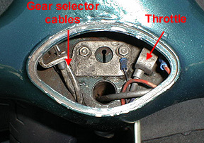
This sections shows how to replace the inner and outer cables for the gear selector box/ throttle slide assuming that the cables are ready for the trash.
I find it is easiest to simply remove the gear end of the twist grip to get the ends of the cables out at the headset end. Using a 10mm socket, remove the central bolt.
Once the pulley is removed, save the spring washer and locating washer that remain on the twist grip end for the rebuild. Move the cables so that the little "top hat" ends to the outer cable disengage from their supports as shown above. Pull the cable inner out of the outer with a pair of pliers. Once it is out you can clip the head of the outer cable to get rid of the crimped metal end as this could get caught as you pull it through the frame.
If you are just removing the inner cable then replace the top hat over the cable outer end, lubricate the new control cable inner with oil, and then thread the new inner in to the existing outer cable all the way until you see it at the selector box end.


If you are also replacing the outer cable you can clip the head of the outer cable to get rid of the crimped metal end as this could get caught as you pull it through the frame as shown in the next few shots.


Clean the end of the old cable outer and wrap in a spiral motion with a piece of electrical tape. This type of tape works well because you can stretch it to make it really tight. Take the new cable outer and place it face to face with the old and continue the wrap around it for about 3 inches. Repeat the process in the other direction (from the new to the old). Once this is secure it should look like the picture above.


At this point a helper is really handy. One person holds the cable at the headset straight up in the air. At the other end you pull the cable slowly through the frame as person number 2 feeds it in. It should slide right through and poke out the proper hole near the engine. The red arrow above shows the old cable outer and the green is the new cable outer. Carefully unwrap the tape from the cables and move on to the next step of threading the inner cable.


Thread both inner cables with the cable top hats in place and set the hats in the support in the headset. Then carefully fit the end nipples in to the pulley in the same direction as they were removed.


Refit the dished washer and then the locating washer, and make sure the small hole in the pulley engages with the peg on the locating washer.


Refit the pulley and tighten the 10mm nut. Place the twist grip in the neutral position and then move down to the selector box end of the cables.


I've switched the model of the bike in the photos but the idea is the same. At the bottom end thread the cable inner around the selector wheel, through the nipple at the end, and then pull it tight. When you pull it make sure the twist grip doesn't move from the neutral position, and be sure the bike is also in neutral at the motor end. Make sure the cable outer is weal seated in the adjuster and that the threaded adjuster is about 1/2 way out so you can adjust it in either direction if needed.


Using a 7mm wrench for the nipple bolt and an 8mm wrench to stop the nipple from turning, tighten the nipple down. It is helpful to have a helper still pulling on the cable to keep it tight. Do the same thing for the other cable and then wiggle the twist grip without actually engaging gears. There should be about an 1/8" of movement. If there is too much movement, equally back out both the adjusters at the selector box. If there is too little, turn them both in enough to get the wiggle.
 Note: An alternative to this method to replacing outer cables is to get an extra long control cable from a bicycle dealer (the type used on tandem bikes). Thread it through the new outer cable first so that the nipple is tight against the outer cable end. Then thread the inner in to the old outer cable still in the bike. This will get you the same result as taping the two outers together as shown above. From here, go to the selector box end and place a gear nipple on the inner cable. Now you can pull the old cable outer and the new cable outer will replace it. Once the new cable is in position, remove the nipple and the tandem inner.

Sunday 20 May 2012

Clutch Cables Forum - may pertain later


Reply with quote
Sat Jul 26, 2008 3:28 pm
Hi everyone, so the first few weeks of owning this little beast have been amazing but not trouble free.

First a broken cable for downshifts from 4-3-2-1 so I was stuck in 4th gear, thankfully very close to home. Took it to the shop and since I negotiated a 6 month warranty they fixed it.

Second my front brake was almost non-existent and every time I shifted into first gear the horn gave it a little "beeep". Highly embarassing but OK The shop fixed the two issues as well.

Third, last night while riding I noticed it was hard to shift through gears so I called the shop and they told me to adjust the clutch cable by the engine but when I looked at the cable by the handle I realized that I am on my last two threads.

I will take it back to the shop so that they replace the cable but I'm worried that it will happen again. It's puzzling because I never had an issue with the clutch cable on my 1978 P125X. Is this a common issue and is there a permanent cure?

Thanks and I love reading this forum!

Reply with quote
Sat Jul 26, 2008 5:49 pm
if your cable is wearing up by the lever it is either that is has no lube or never been lubed, and or the adjuster has a burr it it and is wear/cutting the cable. ensure the cable is not run to create over binding it should have enough to be flexible from the lever down the the body. no tension. when you get the new cable a little squirt once a month of some white silicone grease at the barrell going into the lever should help for premature wear.


Reply with quote
Sat Jul 26, 2008 7:21 pm
Hi Mate, It not a common issue Could be crap cables or your adjustment is way to tight at the adjustment screw? This happens when not enough tension is taken from the clutch arm nipple (Your first step of installing a clutch cable).

When you replace your cable make sure to grease the whole cable with white lithium grease (Panef) Or better.

Make sure you a getting good cables too there is a lot of shite on the market. Your clutch cable should have a fat nipple or nipple insert on it. Keep away from crap cables. I have been using bicycle cables for clutch, gears for years.

*Be sure it's routed correctly (Nipple sitting flush in your lever) Also check for the two wave washers that fit either side of your lever.

If you are in the US or Canada i can call you and talk you through it 10 mins or less and done

Cheers
Reply with quote
Sat Jul 26, 2008 8:20 pm
Replace both the inner and outer cable.

Unlike the throttle and shift cables (they have a separate nipple that the outer cable's metal bushing fits into), the clutch is comprised only of the outer's metal bushing that presses against the metal in the headset.

Eventually that bushing compresses (especially if the clutch adjustment is too tight) and will start to split. That will rub the inner cable and cause it to fail prematurely.

HTHs

\osc

How a vespa Engine Works Video

 
 1964 VNB 4 speed 125cc engine

Pictures of the Red & White 1967 Vespa with the sides off

Took her for a spin today for the first time !.. still needs some tweaking


Electrical

Well this will be a work in progress - the books show a good diagram unfortunately that has very little to do with how my bike is wired so for a start a few pictures of parts - my plan is to clean this up over the next few days


Toyota Relay 12v 90987-02006 / 056700-6912  Denso

General Wiring on Battery Side

Can't seem to find the replacement for these if anyone knows where to find them please let me know

KT Flasher 10w x 2 + 1.7 W Relay
12 Volt 1.5 Amp Trickle charger & Canadian Tire 9-BS Eliminator Battery